High Current Injector Program
The High Current Injector (HCI) project was envisaged to overcome the low current limitation of the Pelletron Accelerator and to provide varieties of ion species like Nobel gases etc. which are not possible with the existing Pelletron Accelerator. The high current from HCI will not only reduce the number of shifts needed for carrying out the experiments but will also enable users to carry out very low cross-section nuclear reactions studies which are not possible using beams from Pelletron due to its low current limitations. The HCI would use a Radio Frequency Quadrupole (RFQ), Drift Tube Linac (DTL), and low beta superconducting cavities to accelerate heavy ions having A/q ≤ 6, from the high-temperature superconducting electron cyclotron resonance ion source (HTS-ECRIS called PKDELIS) to the existing superconducting linear accelerator (SC LINAC). The DTL has been designed to accelerate ions from 180 keV/u to 1.8 MeV/u, using six Interdigital-H (IH) type RF resonators operating at 97 MHz. The required output energy of the DTL is decided by the minimum input velocity (beta = 0.06) required for the existing superconducting LINAC. IH-type resonators are the preferred choice for multiple gap DTL applications due to their high shunt impedance. Acceleration from 180 keV/u to 1.8 MeV/u would be done by six independently phased IH-type RF cavities.
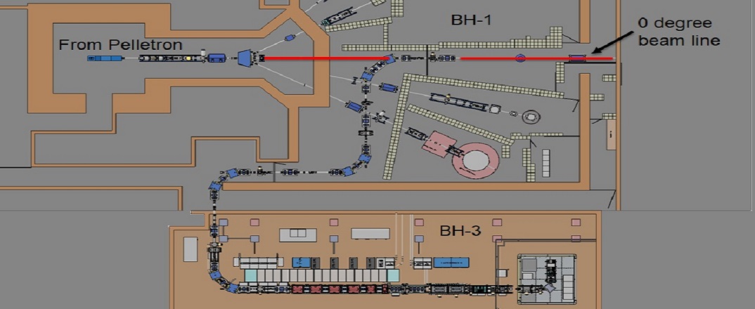
Schematic layout of the HCI
Recent Developments/Results
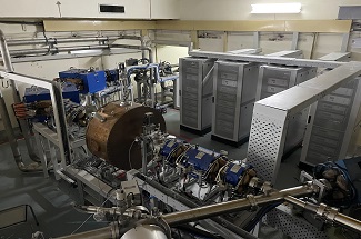
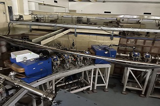
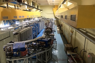
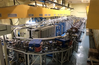
The installation has been completed and HCI beam line has been coupled with SC linac. All required utilities like water, electrical, remote control and magnet power supplies have also been installed and tested. We plan to inject beam in HCI by end of July 2023 and test all diagnostic elements.
More Details
High Temperature Superconducting ECR Ion Source
The ion source has been specifically designed to produce high currents of highly charged ions to provide varieties of ion species like noble gases etc. which are not possible with the existing Tandem accelerator. The high-temperature superconducting-electron cyclotron resonance ion source (HTS-ECRIS) called PKDELIS, which was designed and developed mainly in collaboration with Pantechnik to operate at 14.5 and 18 GHz, consist of HTS coils of Bi-2223 and a permanent sextupole magnet to produce an axial and radial magnetic field, respectively. The PKDELIS source using HTS coils is operational at a higher superconducting temperature of 20 K and requires a simpler cryostat and water-cooled cryo-cooler. The maximum axial magnetic field produced by HTS coils operating at their maximum current is 1.8T and 1.5T at the injection and extraction sides of the ion source, respectively. The maximum radial field on the chamber wall is 1.35 T.
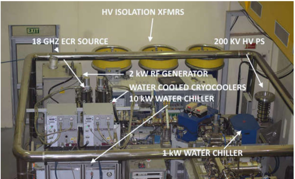
Figure 1: A view of the ion source and related components installed on 200kV high voltage platform
The source is powered by an 18 GHz, 1.7 kW klystron generator. The plasma chamber and the bias tube are water-cooled using a dedicated, portable, closed-cycle water cooling system. The 30kV extraction system comprises the plasma electrode, puller electrode, focus electrode, and the last electrode with the same potential as the puller electrode. The extracted ions are being analyzed by a small, medium resolution, large acceptance, air-cooled, 90° analyzing magnet of banding radius 300mm. A view of the ion source and related components installed on a 200kV high voltage platform is shown in figure 1. A typical charge state distribution of argon plasma at 300W power is shown in figure 2
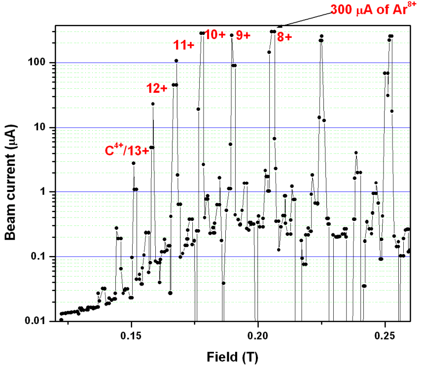
Figure 2: Charge state distribution of argon plasma at 300W power.
Radio Frequency Quadrupole
The Radio Frequency Quadrupole (RFQ) is designed to accelerate ions beam of A/q 6 from 8keV/A to 180keV/A at the low operating frequency of 48.5MHz in continuous-wave (CW) mode to preserve beam intensity. A rod-type structure has been selected in our case because the dimension of the RFQ cavity has become smaller. Further, the design and tuning of this type of RFQ are expected to be much simpler than vane-type RFQs. We adopted the "linear /2-RFQ" structure that was originally proposed in 1985 by a group of Frankfurt University. To further reduce the total length of the structure, the buncher and shaper sections were eliminated, instead, a three-harmonic saw-tooth multi harmonic buncher has been placed ahead of RFQ. The RFQ electrode structure is 2.536m long and 4-rods are supported by 8 stems on a 50mm thick copper base plate and the minimum aperture is 12mm, a 3D model and the assembled photo is shown in the figure 1. RFQ structure consists of precisely machined modulated copper vanes mounted on copper vane posts.
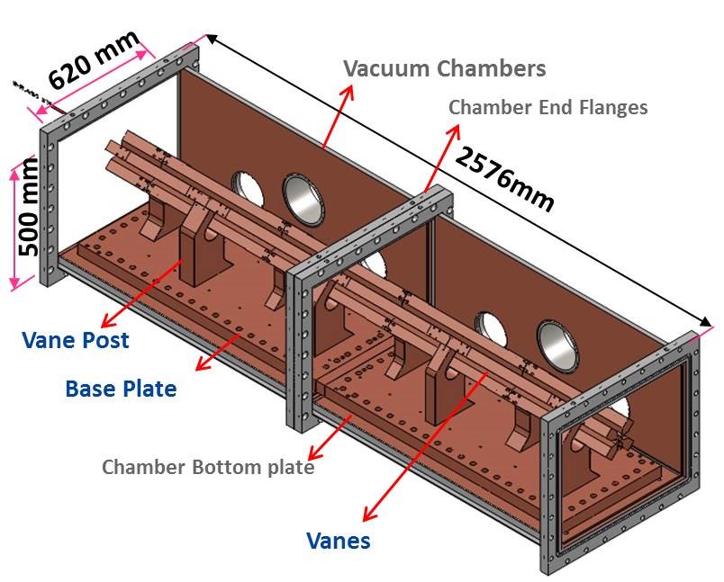
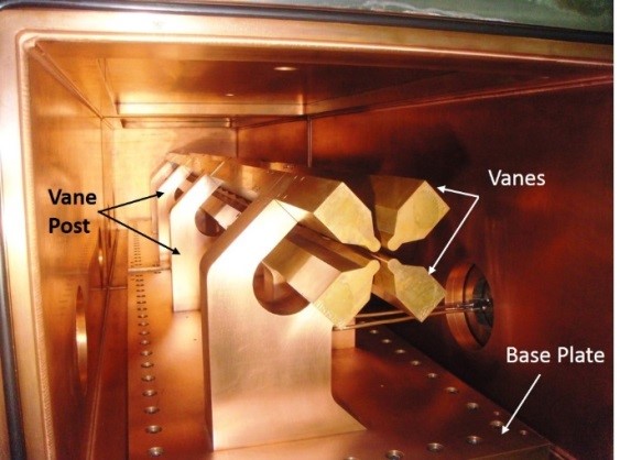
Figure 1: (left) A 3D CAD model view of the RFQ (right) RFQ inside view after Assembly
The whole assembly is done on copper base plates mounted inside copper-plated stainless steel vacuum housing. For ease of fabrication, the vacuum housing, and the base plate, both have been made in two parts and assembled. The vanes and the vane posts have cooling holes for the circulation of water during high power operations. The cooling of base plates and vacuum chambers is done by mounting cooling plates on their outside surface.
Table 1: Key design parameters of the 4-rod Radio Frequency Quadrupole
| Frequency | 48.5MHz |
| Bore Diameter | 12mm |
| Inter electrode voltage | 70kV |
| Charge-to-mass ratio | =6 |
| Injection energy | 8keV/u |
| Output Energy | 180keV/u |
| Length of the electrode | 2536 mm |
| Chamber dimensions | 2576*620*500 mm |
Beam acceleration through RFQ:
Beam acceleration tests have been performed by injecting He2+, O6+, Ne8+, and N5+ ion beam into the RFQ. The output beam energy is estimated from the momentum spectrum of the beam, which was taken with the bending magnet. The estimated output energy of the He2+ beam was 707keV ± 3% at 13kW of power, this is in fairly good agreement. The input and output beam current was measured with Faraday cups. The beam transmissions of He2+ approach sharply from zero to 90% at 13kW and stay constant afterward. Whereas the beam transmission of O6+ reaches a maximum of 23kW. Successful acceleration of ion beams from 8keV/A to 180keV/A validates the design of RFQ modulation
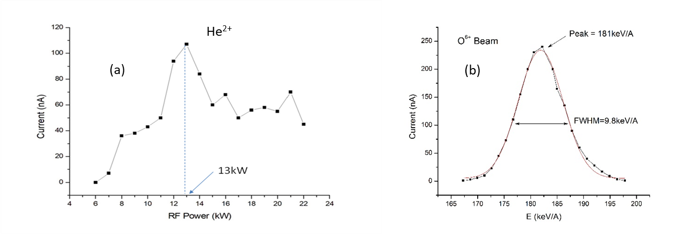
Figure 3: (a) Beam intensity of the accelerated dc beam of He2+ ions as a function of forwarding power, beam transmission is maxim at 13kW. (b) Scan of the beam intensity of O6+ ion beam as a function of the magnetic field of the analyzing magnet. Gaussian fit to the distribution gives final energy of 180.5keV with an energy spread of FWHM of 4.8keV with 3mm slit at object and image plane.
Table 3: Accelerated beam parameters of radio frequency quadrupole
| Beam | Ein(keV) | Eout (keV) | ECavity Pickup (mV) | Peak Power (kW) | |
|---|---|---|---|---|---|
| He2+ | 2.0 | 32 | 707 ± 3.0 | 38.2 | 13.2 |
| Ne8+ | 2.5 | 160 | 3640 ± 2.8 | 43.0 | 18.0 |
| O6+ | 2.67 | 128 | 2896 ± 2.7 | 43.5 | 18.3 |
| N5+ | 2.8 | 112 | 2520 ± 2.5 | 44.8 | 21.2 |
MEBT Spiral Buncher
A 48.5 MHz spiral buncher has been installed in the MEBT section of the HCI beamline to provide the longitudinal beam matching at the entrance of the Drift Tube Linac (DTL) after successfully validating the design. The cylindrical chamber was fabricated of copper-plated stainless steel, while OFHC copper was used for the inner components. The measured quality factor, shunt impedance, resonance frequency, electric field profile, and power requirement matches very well with the simulated value. The bead-pull technique has been used to validate the electric field profile and to determine the various low-level RF parameters. A fine tuner has been developed and employed to correct the frequency shift during the high-power operations in the phase and amplitude lock condition. The cavity has been tested up to the full power of 1 kW to produce 27 kV across each gap.
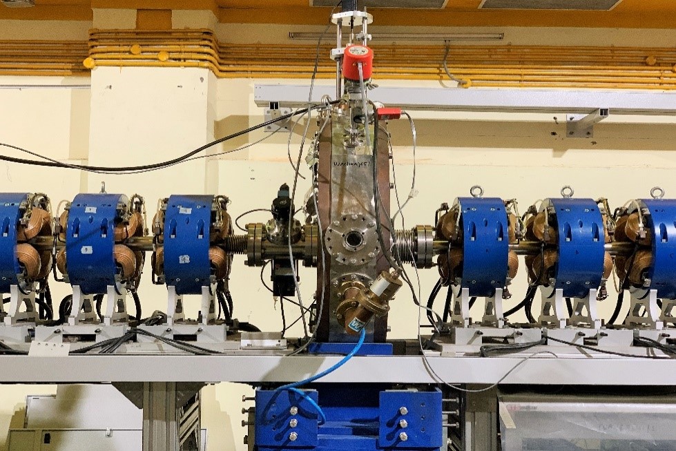
Figure: The commissioning of the MEBT spiral buncher cavity
The X-ray energy spectroscopy method was used to measure the gap voltage experimentally. The data analysis was carried out to find out the endpoint of the Bremsstrahlung spectrums. The endpoint of the Bremsstrahlung spectrum provides the information of maximum gap voltage across the drift tube. The various X-ray spectrums were fitted using a standard Bremsstrahlung equation at different power levels. The error between analytically calculated and experimentally measured gap voltage is ~5%. The cavity has been successfully tested with the beam. The bunched beam was accelerated through DTL-1 to get a designed energy gain of 325 keV/A, with spiral buncher (SB) off. After optimizing the beam transmission through DTL-1 the SB was powered and tuned. The measured current was increased by a factor of two indicating a bunching effect. The cause of low transmission through DTL-1 was large bunched width at the entrance of the SB, ~7 ns. Since the acceptance of the SB is 2-3 ns, SB cannot provide efficient longitudinal matching at the DTL-1 entrance. The bunch length could not measure after the spiral buncher since there is no longitudinal diagnostic device is available, in the MEBT section of HCI.
IH Drift Tube Linear Accelerator
The Drift Tube Linac (DTL) has been designed to accelerate ions from 180 keV/A to 1.8 MeV/A, using six Inter-digital H type RF resonators operating at 97 MHz (figure 1(a)). IH-type resonators are the preferred choice for multiple gap DTL applications due to their high shunt impedance values. Acceleration from 180 keV/A to 1.8 MeV/A is done by six independently phased IH-type RF cavities. The beam dynamics and generation of the drift tube geometry are done using the LANA code. The electrical design of the first resonator tank has been done using CST Microwave Studio. Each IH tank is independently phased from separate rf amplifiers. Except the first and last tanks the tanks consist of bunching sections and accelerating sections. The accelerating sections in the IH tanks are designed for 00 synchronous phase, see figure 1(b).
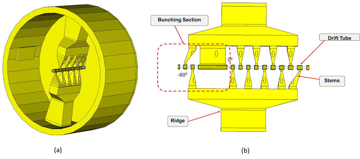
Figure 1: (a) A 3D view of the Inter-digital H type drift tube linac structure. (b) A front view of the DTL showing 2-gap buncher section followed by a long drift tube.
The beam is injected into the accelerating sections with a reduced phase spread and velocity higher than the design velocity so that the bunch drifts to more negative phases during acceleration and emerges with a reduced energy spread. Quadrupole triplets between tanks provide periodic transverse focussing. The parameters of the DTL cavities are listed in table 1.
Table 1: Number of cells and cell length, output energy and power required to accelerate the ion beam of A/q = 6 through DTL-1 to DTL-6 cavities
| Tank No. | Length | No. of Cells | Eout (MeV/A) | Power (kW) |
|---|---|---|---|---|
| 1 | 38.7 | 11 | 0.32 | 5 |
| 2 | 69.3 | 13 | 0.55 | 11 |
| 3 | 89.6 | 13 | 0.85 | 18 |
| 4 | 93.6 | 11 | 1.15 | 18 |
| 5 | 91.7 | 11 | 1.46 | 24 |
| 6 | 82.0 | 9 | 1.80 | 25 |
Beam acceleration through DTL:
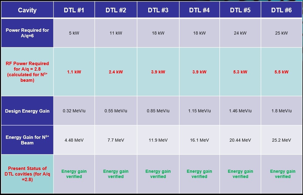
After the high-power conditioning of the DTL tanks, beam acceleration tests have been carried out using the N5+ beam. The power level required by DTL-1 to DTL-6 cavities for N5+ was calculated to be about 1.1 kW, 2.4 kW, 3.9 kW, 3.9 kW, 5.3 kW, and 5.5 kW respectively get the designed energy gain. An accelerated beam of energy 180keV/A is rebunched by a spiral buncher. The bunched beam is injected into DTL tanks. Beam tests have been carried out in a stepwise manner to carry out the energy gain measurement from RFQ and DTL structures.
Table 2: Forward and pickup required to accelerate the N5+ bunched beam through cavities
| Cavity | Forward Power | Pickup Power (mV) | Eout (MeV/A) |
|---|---|---|---|
| RFQ | 20.2 kW | 41 | 0.18 |
| SB | 300W | 112 | 0.18 |
| DTL-1 | 1.23 kW/td> | 44.8 | 0.32 |
| DTL-2 | 2.43kW | 25.6 | 0.55 |
| DTL-3 | 4.98 kW | 40.1 | 0.85 |
| DTL-4 | 3.98 kW | 32.6 | 1.15 |
The ion beam has been accelerated successfully through DTL-1 to DTL-4, the energy gain through these 4-tanks is 0.32MeV/A, 0.55MeV/A, 0.85MeV/A, and 1.15MeV/A. The energy is confirmed by an achromat bending magnet installed at the end of DTL-6. The beam current was optimized by tuning the amplitude and RF phase of the MHB, RFQ, SB, DTL1 to DTL4.
Group Members and Contact Details





Last updated on 13/05/2025


