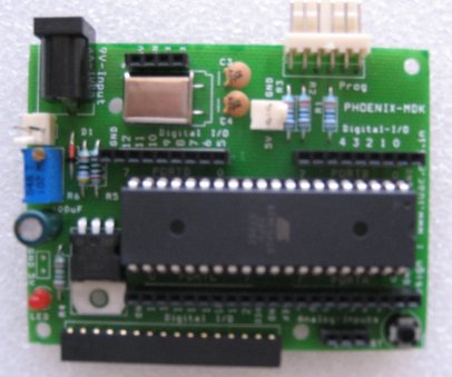
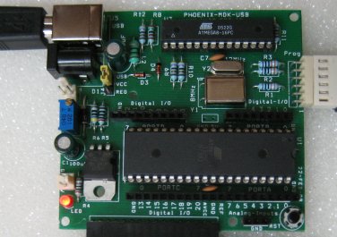
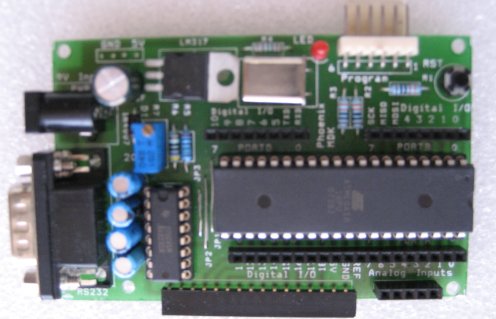
The simplest way to
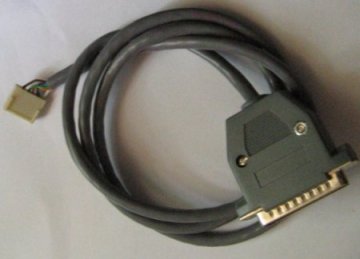
program all the three models are through the PC parallel port, The
white six pin connector is connected to the PC parallel port using a
cable with the following connections.
ATMEGA16
|
6 Pin Con
|
25 Pin D Con.
|
PC Parallel Port
|
|
Reset(9)
|
6
|
16
|
Init
|
SCK(8)
|
5
|
1
|
Data0
|
MISO(7)
|
4
|
11
|
Busy
|
MOSI(6)
|
3
|
2
|
Strobe
|
Ground(11)
|
1,2
|
18
|
Ground |
The
serial and USB versions can be easily interfaced to a PC. They can also
be programmed through the
serial/USB ports after uploading a bootloader program to ATmega16. A
jumper option allows the USB version to use the 5V supply from
USB.
The LCD display is useful for
program
development. Library routines are available to output data to the LCD
display. Here is a photograph of LCD display , connected to
the USB version and drawing 5V DC supply from USB. The PMDK board can be interfaced to a PC using RS232
or USB ports (USB communication is handled by a USB to Serial converter
implemented using ATmega8, by Igor
Cesko)


